Here we are : first attempt to create a board with a micro-controller.
We are going to start simple, by building the "Hello World" for electronics : the flashing LED.
What do we need ?
- an Atmel MCU (it will be an ATmega8, because this was the smallest model my local hardware retailer had in stock)
- all ancillary components (full liste will come later)
- a breadboard, since we are going to modify our first realization in soon to come experiments
- a development environment for AVR MCUs. My suggestion is WinAVR (http://winavr.sourceforge.net/), since it is open-source, free and very good
- an ISP cable (see articles Garder le contact and In Situ Programming)
The schema
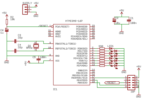
No magic here : all this is more or less taken from the datasheets and application notes.
Power supply
To keep it the simplest possible for the moment, the 5V needed by the circuit is provided by an regulated power supply, so no regulator is present. C1 and C2 capacitors filter the external supply, to eliminate all perturbations which could be caught by the wires.
Si you plan to power the circuit with a 9V battery, or a rechargeable pack, have a look first to this other article.
The outputs
There is a LED and its resistor (R3) connected to each pin of port D, so 8 LEDs and 8 resistors.
R3 value is computed as follows :
| port output voltage | 5V |
|---|---|
| LED voltage drop | 1.8V |
| current through the LED | 10mA |
BEWARE : do not exceed 20mA at the most for the Atmel pins output current. So high power LEDs are not welcome here... It low current LEDs (2mA for instance) are used , the above computation must be adapted to suit the characteristics of your component.
A quick glance to the Ohm law tells us that R3 = (5 - 1.8) / 0.01 = 320 . We’ll choose the closest normalized value above this value, which leads to 330 ohm.
Programming connector
ISP (In-Situ Programming) is the programming connector. Its pinout matches the cable I use, so maybe you’ll have to adapt it for your cable, based on the position of the signals used.
Supply decoupling
C5 is a decoupling capacitor, aimed at eliminating HF perturbations generated by all these chips. The recipe taught by my Master for this kind of filter is : "put a 100nF capacitor between Vcc and ground, the closest possible to the involved chip".
Quartz oscillator
C3, C4 and Q1 build the external quartz oscillator circuitry, which defines the MCU clock frequency. The selected quartz is a 8MHz one. The value of capacitors (33pF) is defined by the MCU datasheet. These 3 components must be located as close as possible to the MCU.
Reset circuitry
R2 and C6 are used to hold the reset input pin when powering on the circuit, to avoid erratic behaviour of the MCU during the supply voltage stabilization phase. The working principle is simple :
- when power is applied to the circuit, C6 is discharged
- it will charge through R2, and thus the potential applied to the /RESET input will be null at start, and then will increase while the capacitor is charging, up to 5V when it will be fully charged (since there will be no more current flowing through R2).
The /RESET input triggers a MCU reset when it is at low level. So we will obtain here some kind of "delayed release" of the MCU, leaving enough time for the Vcc voltage to stabilize after power on before letting the beast doing its job.
Note: the /RESET notation means the the input is active low, ie. when its state is 0 ("/" means "NOT").
Here we are. This is not so complicated after all ;)
Practical realization

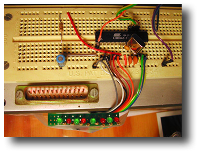
We can see here the breadboard with the few chips playing the game.
I have soldered the LEDs and their resistors on a small prototype board, since this kind of sub-assembly could be reusable in other experiments as a display, or a debug helper.
Source code
Two versions of the code have been written :
Basic version
This version is named "Newly Born Young Padawan", and manage delays using active loops. It is obvious that such a method must not be used in a real program (apart if it is a chaser like here ;), since the MCU can does nothing else during the wait times.
Advanced version
This is the "Young Anakin" version. It is based on timers/counters of the MCU and makes use of the associated interrupts for the LEDs pattern changes. This is the Bright Side of the Force.
Source code being abundantly documented, it is up to you now to study them.
The conclusion
Mission complete Chief !! (private joke)
Components list
| - Label - | - Value - |
|---|---|
| C1 | 100nF |
| C2 | 10µF |
| C3 | 33pF |
| C4 | 33pF |
| C5 | 100nF |
| C6 | 1µF |
| IC1 | ATMEGA8-16P |
| LED1 | standard LED |
| Q1 | 8MHz |
| R2 | 10kOhm |
| R3 | 330 Ohm |
| SV1 | HE10 connector |
 PoBot
PoBot
 The very first steps


